Skip to content

Static Lighting and Dynamic Lighting

An LED can be lit using one of two methods: the static lighting method, in which a constant current is input continually over time, and the dynamic lighting method in which current is fed in continuous ON-OFF pulses. When the ON-OFF intervals are short, dynamic lighting appears to the human eye as static lighting. Figure 7 shows an operational comparison between static lighting and dynamic lighting, showing the constants for real circuits using static lighting and dynamic lighting.

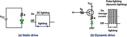
Figure 7 (a) and (b) – Static lighting and dynamic lighting drive examples.

Selecting A Lighting Method Static lighting and dynamic lighting are mainly used in the following types of applications.
Application Viewing Angle 2?1/2
High-Brightness LED information panel 15° to 30°
Signal applications 8° to 30°
Low-Brightness LED information panel 30° to 120°
Narrow-Direction indicator 30° to 60°
Wide-Direction indicator 60° to 120°
Automotive stop lamp 20° to 50°
Automotive dashboard narrow directionality 20° to 60°
Automotive dashboard wide directionality 60° to 120°
Dynamic Lighting Frequency To make dynamic lighting appear continuous (to a stationary observer), use high-frequency lighting. However, if the lighting frequency falls below a certain value, the naked eye will register flickering. In the case of sine wave lighting (now widely used) or square-wave lighting, flickering appears when the frequency falls to below 50 Hz; at around 40 Hz, flashing can clearly be seen. Therefore, to avoid any problem, select a lighting frequency of at least 100 Hz. When the observer is being jolted (for example, if he is riding in a car or walking) or being photographed by a camera of some kind, flickering will be apparent, even if the lighting frequency is quite high. Select a lighting frequency according to the application. Static Lighting The circuit in Figure 7(a) illustrates an example of static lighting in an LED lamp used as an indicator. The LED lamp characteristics are based on the technical data given in the appendix at the end of this Application Guide. Task: When illuminating an LED lamp using a 10-mA forward current, calculate the forward voltage (which should be approximately 2V) using the LED lamp characteristics diagram (Forward Voltage – Forward Current). Design: With a power supply voltage (Vcc) of 5 V and a resistance R as shown in Figure 7, the voltage drop Vr is: Vr = Vcc – (forward voltage) = 5.0 – 2.0 = 3.0 V. Therefore, when a current of 10 mA is run to the resistor, the resistance R is:R = 3V/10 mA = 300 W. Confirmation: After calculating the resistance R, check as following: Is there a problem if the power supply voltage fluctuates? select as the value of R the closest resistance value of an LED in the LED series. Dynamic Lighting For dynamic (pulse) lighting, bipolar transistors, FETs, and dedicated ICs are generally used. The circuit in Figure 7 (b) illustrates an example of pulse lighting. The transistor used in the circuit is a 2SA1298(Y) transistor, the LED lamp forward current is 80 mA, and the power supply voltage (Vcc) is 5 V.

Figure 13 – 2SA1298 Transistor characteristics

Task: The base current (Lb) used for the 80-mA transistor collector current(Ic) is about 1 mA, based on the characteristics curve in Figure 13. Since the transistor voltage Vbe is normally 0.7 V, the resistance Rb in the circuit Figure 7 (b) is: Rb = (5 – 0.7)V/1 mA = 4.3 ohms. Setting Ib to 2 mA to stabilize the circuit results in: Rb = (5 – 0.7)V/2 mA = 2.15 kohms. Thus, a resistance of 2.2 kohms is adequate.

View Products

Find something you were looking for? Get a free no-obligation quote today.